BACK
Assignment 3
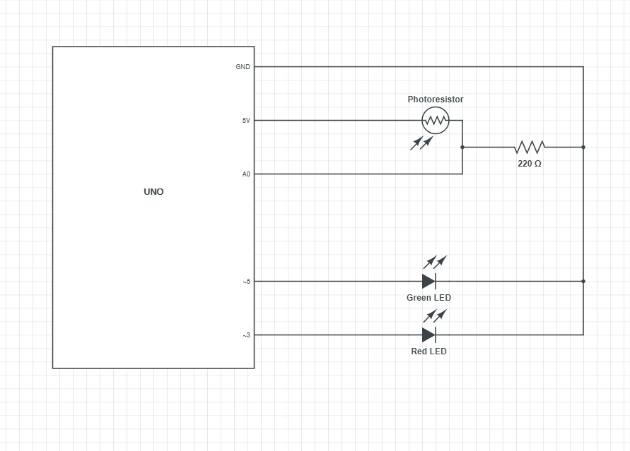
This is the schematic for my circuit. I choose a to use a 220 Ohm resistor because the RED LED has a voltage drop of 1.8V, which is a lower voltage drop than the GREEN LED, and a desired amp of 0.02A. Given the equation, V=IR the optimal resistor is 160 Ohms. The closets resistor I have to that value is 220 Ohms.
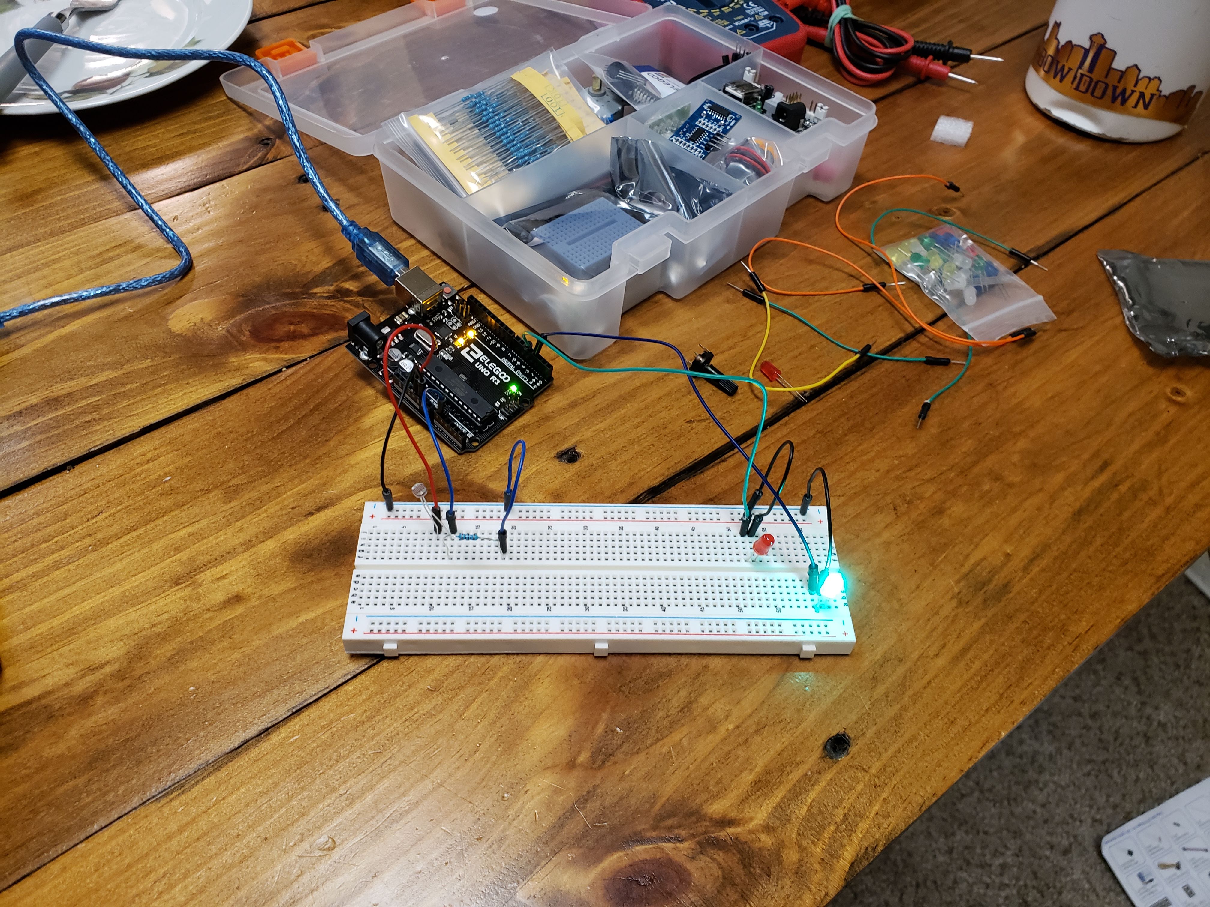
This is my circuit. I am using a photoresistor to toggle on the GREEN and RED LED. When the photoresistor receives average room lighting, the GREEN LED receives the 5V. And when the photoresistor receives less than average room lighting (covered), the RED LED receives 5V.
            //defining variable sensorValue as 0

            int sensorValue = 0;

            //defining variable outputValue as 0

            int output = 0;


            //setup function

            void setup() {

            //setup serial

            Serial.begin(9600);

            }


            //loop function

            void loop() {

            //reading and storing sensor value

            sensorValue = analogRead(A0);

            //converting sensor value range

            output = map(sensorValue, 50, 100, 0, 255);

            //constraining output to be between 0 and 255

            output = constrain(output, 0, 255);


            //if statement for turning on either the red or green LED

            if(output > 100){


                //if the photoresistor is receiving at least the average amount of light in my room the green LED is on

                analogWrite(3, 100);

                //and the red LED is off

                analogWrite(5, 0);


            }

            //else statement for red LED

            else {


                //if the photoresistor is not receiving at least the average amount of light in my room the red LED is on

                analogWrite(5, 100);

                // and the green LED is off

                analogWrite(3, 0);


            }


            //serial print statement for text

            Serial.print("LED= ");

            //for the output variable value

            Serial.println(output);


            //delay 5ms

            delay(5);

            }
This is the code I used in Arduino to create this circuit. I used Serial to log the values of my photoresistor and LEDs. I used analogRead to read the photoresistor value. I used map and constraint to convert the photoresistor value to an LED value. And I used to analogWrite to write to each LED the desired value./p>
This is the gif of my circuit in operation. WHen the photoresistor is uncovered the GREEN LED is on. When the photoresistor is covered the RED LED is on.