BACK
Assignment 4
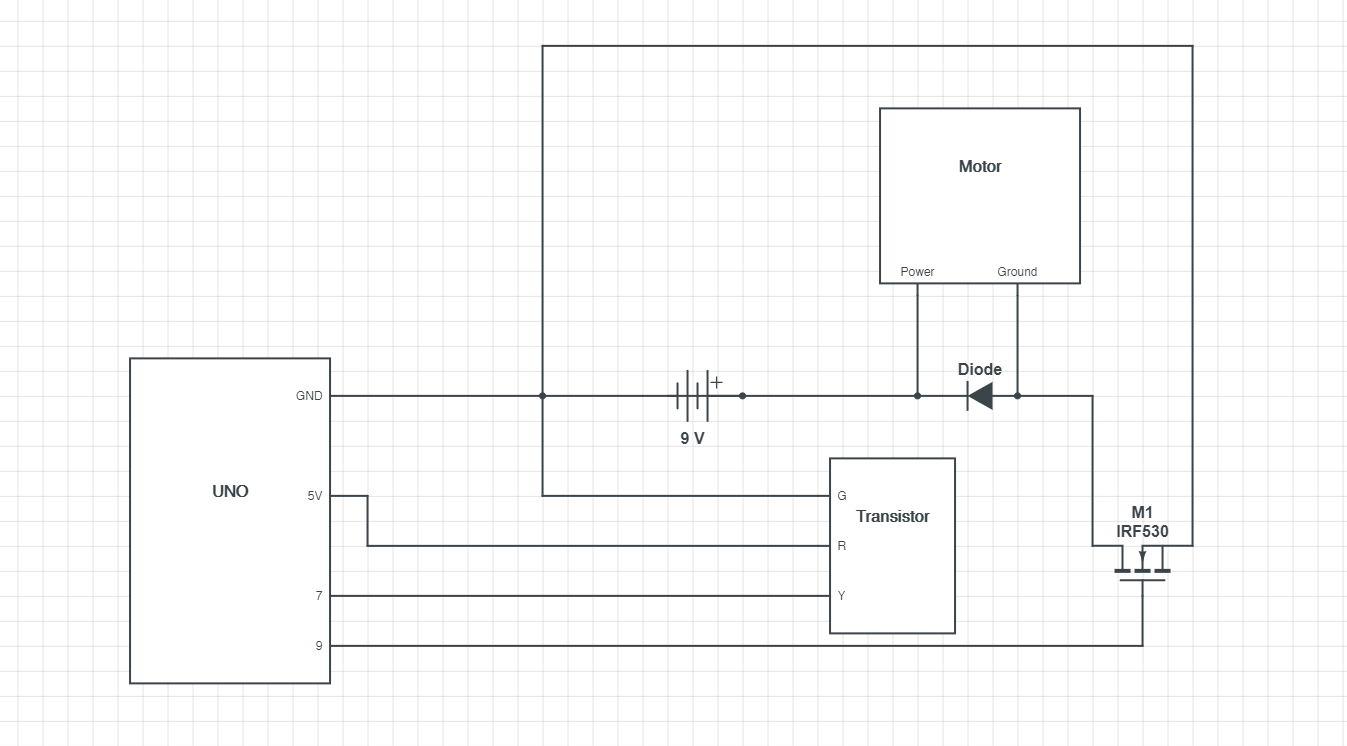
This is the schematic for my circuit. I used a 9V/18W external power source to power the motor with a N-MOSFET transistor to control the motor. The N-MOSFET transistor is connected to pin 9. With a 9V and 18W power source the current is 2A (P=VI). This is the voltage/current that is expected to be found in the load of the circuit.
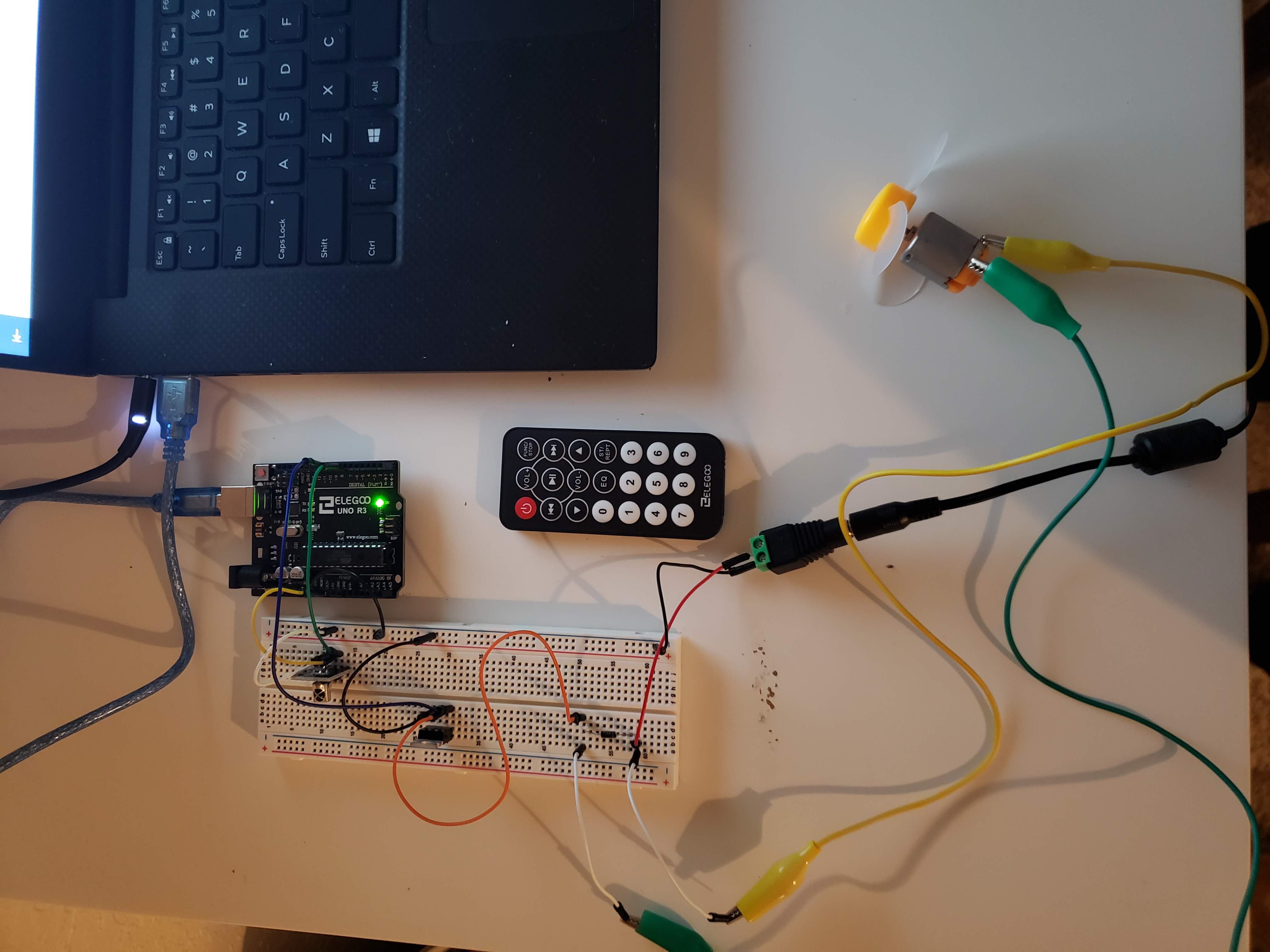
This is my circuit. For the IR sensor it is connected to the 5V power soruce of the UNO board. The onboard IR sensor resistor allows for a direct connection to the 5V power soaurce and ground. This sensor is connected to pin 7.
            //calling IR remote library

            #include


            //defining variable rate as 0

            int rate = 0;

            //defining variable RECV_PIN as 7

            const int RECV_PIN = 7;

            //creating an object for IR protocols and processing of the receiver

            IRrecv irrecv(RECV_PIN);

            //creating an object to decode information from the remote

            decode_results results;

            //defing variable fanPin as 9

            const int fanPin = 9;


            //setup function

            void setup(){


                //IR protocols and processes

                irrecv.enableIRIn();

                //IR protocols and processes

                irrecv.blink13(true);

                //defining pinMode

                pinMode(fanPin, OUTPUT);


            }


            //loop function

            void loop(){


                //if statement checking if information is received

                if (irrecv.decode(&results)){


                    //switch statement to hand IR code

                    switch(results.value){


                        //case 1 for IR input

                        case  0xFF30CF: //Keypad button "1"

                        //defining rate as 50

                        rate = 50;


                    }

                    //reset receiver

                    irrecv.resume();


                }

                //writes to motor the rate

                analogWrite(fanPin, rate);


            }
This is the code I used in Arduino to create this circuit. The IR sensor and pin 7 reads the input from the remote, if it is 1 (one) then it sends a signal to pin 9 and opens the gate in the transistor allowing for current to reach the motor.
This is the gif of my circuit in operation. When I press the number one of the remote the fan turns on.
Code sourced from: http://www.circuitbasics.com/arduino-ir-remote-receiver-tutorial/